
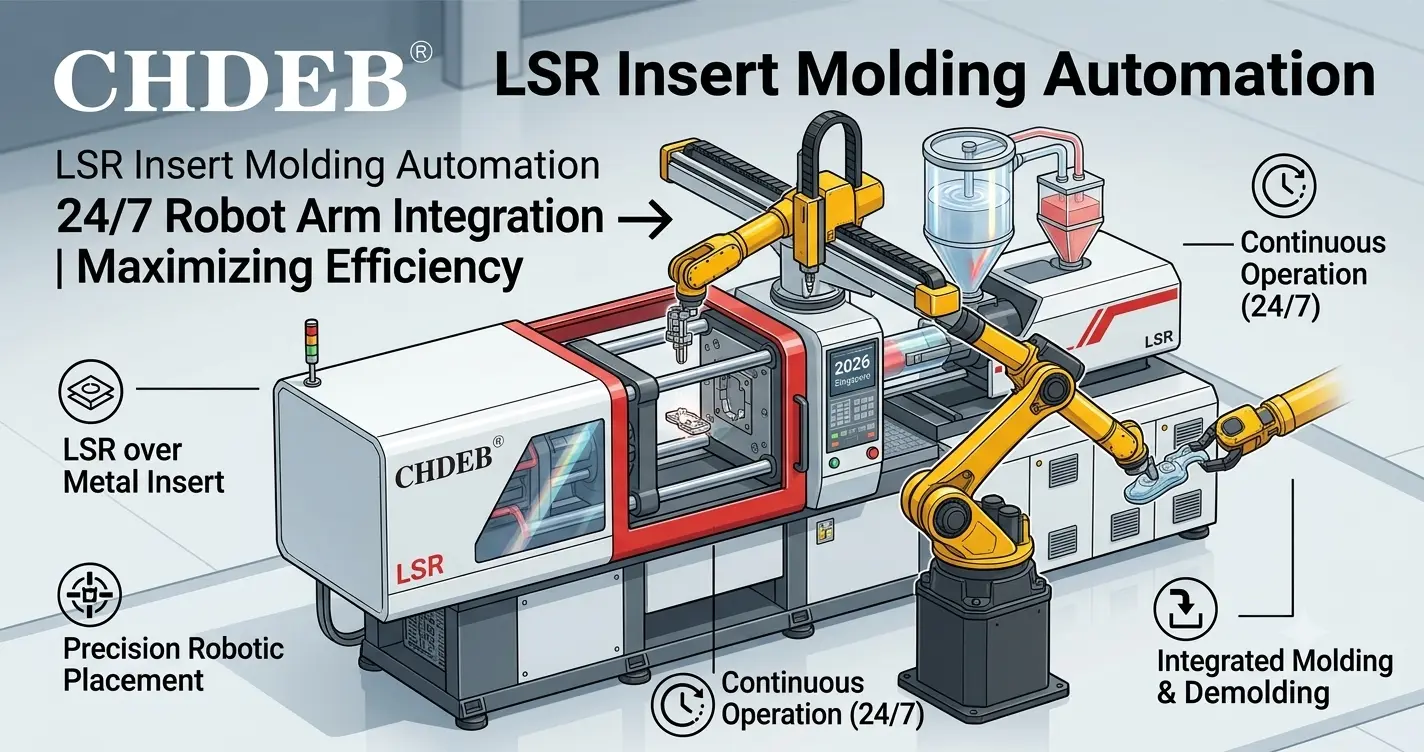
LSR Insert Molding Automation — 24/7 Robot Arm Integration
2026-07-26 10:33
A senior automation engineer at a medical device contract manufacturer in Suzhou described the incident that finally justified their robot integration budget: an operator loading 16-cavity connector insert molds at shift hour six reached into the mold area slightly too early — before the upper platen had fully retracted — and contacted the 170°C mold surface with their forearm. Third-degree burn. Three weeks lost time. OSHA recordable. Line shut for two days during investigation. Total incident cost including workers' compensation, temporary staffing, and lost production: approximately $38,000. The robot cell they installed three months later cost $52,000. It paid for itself in 11 months — before accounting for the burn incident risk they'd eliminated entirely.
LSR insert molding automation isn't only an efficiency story. At mold temperatures of 120-180°C running 22-hour shifts, manual insert loading creates occupational hazard exposure that no engineering control can fully mitigate short of removing the human from the mold zone. An automated vertical LSR machine integrated with a robot arm LSR machine cell does exactly that. This guide, from our engineering team at Debiao (a national high-tech enterprise with 50+ core patents, manufacturing LSR equipment since 2013 from our 30-acre facility in Ezhou, Hubei), breaks down the architecture of a fully automated double-slide LSR insert molding cell — what it requires, what it delivers, and where the integration challenges actually are.
Contents [ hide ]
The Two Problems With Manual LSR Insert Loading That Automation Solves
What Is the Actual Burn Risk Profile in Manual LSR Insert Molding?
How Does Human Loading Variation Affect Cycle Time and Part Quality?
Why Double-Slide Architecture Is the Required Foundation for Robot Integration
Which Robot Type Works Best for LSR Insert Loading — SCARA, 6-Axis, or Delta?
Do You Need Machine Vision for Insert Placement Verification?
DB-LS2R to Robot Communication: Signals, Timing, and Safety Interlock Design
Automated vs. Manual LSR Insert Molding: Full Production Comparison
Real Automation Cell Configurations: What Factories Are Actually Running in 2026
Where Robot Integration Actually Gets Difficult — and How to Plan for It
The Two Problems With Manual LSR Insert Loading That Automation Solves
What Is the Actual Burn Risk Profile in Manual LSR Insert Molding?
LSR mold operating temperatures range from 120°C for low-reactivity grades to 180°C for fast-cure automotive and medical compounds. Contact with a mold surface at 150°C causes a full-thickness (third-degree) burn in approximately 1 second. At 170°C, the threshold drops below 0.5 seconds — faster than the human pain reflex can trigger withdrawal.
Manual insert loading in this environment requires the operator to work within 200-400 mm of the heated mold surface on every cycle — every 45-90 seconds, for an 8-12 hour shift. A single lapse in attention, a slightly early reach, or a mold slide that cycles before the operator has withdrawn is sufficient to cause a serious injury. These aren't edge-case events. ISO 11161:2007 (safety of integrated manufacturing systems) classifies LSR injection mold zones as "hazardous zones requiring access restriction" precisely because of this risk profile.
According to data from the U.S. Bureau of Labor Statistics (2025), thermal contact burns represent 8.3% of all manufacturing-sector lost-time injuries, with rubber and plastics processing equipment accounting for a disproportionate 14.7% of that category. Insurance actuaries price this risk into workers' compensation premiums specifically — typically adding $0.008-$0.015 per labor-hour for operators classified as "hot mold" workers. On a 3-shift LSR line with 6 operators, that's $12,000- $22,000/year in premium loading alone, before any actual incident cost.
How Does Human Loading Variation Affect Cycle Time and Part Quality?
The second problem is subtler and more expensive at scale.
Human insert loading time isn't constant. It varies by operator, by hour of shift, by number of inserts per mold, and by how fatigued the operator is at hour seven of a 12-hour shift versus hour one. A study of manual loading time on an 8-cavity connector insert mold at a Malaysian silicone component factory (2025) showed the following loading time distribution across 1,200 consecutive cycles:
Mean loading time: 22.4 seconds
Standard deviation: 4.1 seconds
Range: 14 seconds (best operator, early shift) to 38 seconds (tired operator, late shift)
Coefficient of variation: 18.3%
That 18.3% CV in loading time means the machine's effective cycle time varies by the same percentage — directly reducing predictable output capacity. Production planning based on "22-second average loading" produces systematic overtime and missed delivery commitments because the true cycle distribution includes the 38-second tail events that blow the schedule. A robot loading the same 8-cavity mold has a loading time CV below 0.5% across any number of cycles.
Part quality is affected too. When a tired operator loads inserts in hour 11 of a 12-hour shift, positional accuracy degrades. Inserts placed 0.3-0.5 mm off nominal position — consistently within a fatigued operator's capability — cause the wall thickness asymmetry, flash generation, and adhesion inconsistency described in earlier articles in this series. The robot doesn't get tired. Its repeatability is specification-constant: ±0.02-0.05 mm regardless of cycle count or time of day.
⚙️ INSIDER NOTE
Before specifying a robot integration, measure your current manual loading time distribution — not just the average. Time 200 consecutive loading cycles across two different operators and two different shift hours (hour 2 and hour 10). Calculate the standard deviation and the 95th percentile loading time. Your automated cell's takt time must be designed around the robot's consistent loading time, which will be dramatically shorter and tighter than the manual distribution. If you design the cell around your manual average, you're leaving performance on the table.
Why Double-Slide Architecture Is the Required Foundation for Robot Integration
This point gets missed by automation engineers who haven't worked specifically with LSR machines before. Not all vertical LSR press configurations are equally suitable for robot integration.
A single-slide vertical machine — like the DB-LS1R — has one slide table that exits the press, gets loaded, and returns. When a robot is loading that slide, the press is open and idle. The robot's loading time is additive to the cycle — it doesn't overlap with anything. The result is that robot integration on a single-slide machine reduces burn risk and improves insert positioning accuracy, but doesn't improve throughput over a fast human operator. In many cases, a robot that takes 15-18 seconds to load a complex insert configuration will run slower than an experienced human taking 12-14 seconds on the same mold.
The DB-LS2R double-slide architecture changes this calculation entirely. Two slides alternate into the same press:
Slide A: inside the press — mold closed, injecting, curing
Simultaneously, Slide B: outside the press — robot unloading finished parts and loading fresh inserts, simultaneously, with zero time pressure
The robot's loading time is hidden behind the cure cycle — not added to it. When the cure completes, Slide A exits and Slide B enters immediately. The press never waits for loading. The robot never races against the cure timer.
This is the architecture that makes 24/7 unattended operation possible. The robot has the full cure window — typically 30-50 seconds — to complete its loading sequence without any time pressure. On complex insert configurations requiring 6-8 individual inserts per cycle, 30-50 seconds is comfortable. The press meanwhile is molding parts continuously. Zero idle time.
Compare DB-LS1R single-slide and DB-LS2R double-slide for automation suitability →
Anatomy of a 24/7 Automated LSR Insert Molding Cell
Which Robot Type Works Best for LSR Insert Loading — SCARA, 6-Axis, or Delta?
The answer depends on insert geometry and loading complexity. There is no single right answer across all applications — which is why automation engineers who start by specifying a robot type before analyzing the insert handling task get into trouble later.
| Robot Type | Best For | Positional Repeatability | LSR Cell Suitability |
|---|---|---|---|
| 6-Axis Articulated (FANUC, KUKA, ABB, Yaskawa) | Complex insert geometry; multi-angle approach; combined unload + load + vision tasks | ±0.02-0.05 mm | ✅ Highest — preferred for medical and electronics insert molding with varied part geometry |
| SCARA (Epson, Yamaha, Denso) | High-speed planar pick-and-place; simple inserts requiring only XY+Z positioning; compact footprint | ±0.01-0.02 mm | ✅ Good — for flat inserts, single-type molds, high-speed simple loading. Not suitable for multi-orientation inserts |
| Delta (Parallel) (ABB FlexPicker, Fanuc M-1) | Very high speed pick-and-place; lightweight inserts under 1 kg; packaging-style applications | ±0.05-0.10 mm | ⚠️ Limited — speed advantage rarely applicable to insert loading where accuracy matters more than cycle speed |
| Collaborative (Cobot) (Universal Robots, Doosan) | Flexible deployment; human-cobot work zones; easy reprogramming for SKU changeover | ±0.03-0.10 mm | ⚠️ Suitable with caveats — safety-rated slower speed near hot molds; verify ISO 10218-2 compliance for mold zone proximity |
For most LSR insert molding applications in medical, electronics, and connector seal production — where inserts are 2-50g, geometrically varied, and require ±0.05 mm placement accuracy — a 6-axis articulated robot with a payload capacity of 3-10 kg is the industry standard. The FANUC LR Mate 200iD and ABB IRB 1200 are the two most commonly specified in the LSR cell installations I've observed in Guangdong, Jiangsu, and Thailand in 2025-2026.
What End-Effector Design Does LSR Insert Molding Require?
The end-effector is where most LSR automation cell designs fail — not the robot itself. Three requirements specific to hot-mold LSR insert loading:
Thermal isolation: The end-effector approaches a 150-170°C mold surface on every unload cycle. Standard aluminum vacuum cups degrade rapidly at that temperature, and heat conducted through the gripper can damage the robot's wrist joint sensors over time. End-effectors for LSR insert loading should use ceramic or PEEK vacuum cups for the mold-side contact faces, with thermal break inserts between the active gripper elements and the robot flange.
Dual-function design — unload and load in one approach: The most efficient cell design uses a dual-station end-effector: one face holds the demolded finished parts (vacuum or mechanical gripper, depending on part geometry), the other face holds fresh inserts pre-staged from the vibratory bowl or tray. The robot approaches the external slide, releases finished parts to a conveyor, rotates the end-effector 180°, and places fresh inserts — in one approach sequence. Single- function end-effectors that require a separate trip to the parts bin between unload and load are 40-60% slower.
Force feedback or compliance for insert seating: Insert cavities in LSR molds have tight positional tolerances — typically ±0.05-0.10 mm on locating pin clearances. If the robot places an insert with even a 0.08 mm lateral error, the insert may not seat fully on the locating pin. Without force feedback, the robot will apply its programmed force to a partially seated insert — potentially bending the pin or cracking a ceramic insert. A compliant wrist joint (passive compliance, ±1-2 mm float) or active force/torque sensor at the robot flange resolves this without requiring perfect calibration between robot and mold.
Do You Need Machine Vision for Insert Placement Verification?
Short answer: for production volumes above 500,000 inserts/month and for medical or automotive programs, yes. For lower-volume electronics and consumer product programs, it depends on your customer's traceability requirements.
Machine vision in an LSR insert molding cell serves two distinct functions:
Pre-placement verification — a camera checks each insert from the parts feeder before the robot picks it, confirming correct orientation, absence of deformation, and presence of any serialized feature (e.g., lot code, orientation mark). This is valuable for connector inserts where loading a reversed pin into a 6-cavity mold would produce six non-conforming assemblies before the error is caught.
Post-placement confirmation — a camera verifies that each insert is correctly seated in the cavity after the robot places it and before the mold closes. For medical applications where an unseated insert produces a part that may pass visual inspection but fail functional testing, post-placement vision is essentially non- negotiable. The camera cycle adds 0.5-1.5 seconds per slide, which is still within the cure window on most programs.
🟢 PRACTICAL TAKE
If you're deploying machine vision for the first time in an LSR cell, start with pre-placement orientation verification only — it's simpler to implement, faster to validate, and eliminates the highest-frequency error (reversed inserts) with minimal integration complexity. Add post-placement seating verification in phase two once the cell is running stably. Trying to implement both simultaneously on a first installation extends commissioning time by 3-4 weeks and introduces enough variables that troubleshooting any issue becomes difficult.
DB-LS2R to Robot Communication: Signals, Timing, and Safety Interlock Design
This is the section automation engineers need and machine vendors rarely provide in enough detail. The DB-LS2R communicates with external automation through a standard I/O interface — digital signals via terminal block or optional fieldbus (Profinet, EtherNet/IP on request). The signal architecture for a robot-integrated cell follows this sequence:
Press → Robot: "Slide B out, ready for loading" signal
Output from the DB-LS2R when Slide B has fully exited the press and the mold is closed on Slide A. This is the robot's permission signal to begin its approach to Slide B. The robot should not approach the slide until this signal is confirmed — not on a timer, on a signal. Timers drift. Signals are state-based.Robot → Press: "Loading complete, slide B clear" signal
Output from the robot controller when the end-effector has cleared the slide travel path by a defined safe distance (typically 150 mm minimum above the slide surface). The DB-LS2R will not initiate slide B return until this signal is received. This is the primary collision prevention interlock.Press → Robot: "Slide B in, mold closing" signal
Informational signal to the robot controller confirming slide return has started. The robot should be in its home or standby position at this point — if it isn't, this signal triggers a safety hold.Press → Robot: "Cure complete, mold opening on Slide A" signal
The robot uses this signal to begin staging finished part unload from the conveyor discharge position and preparing the next batch of inserts in the end-effector's load station — time it takes before the "Slide A out" signal arrives is used for pre-staging, not wasted.Emergency stop interlock — bidirectional
The robot cell's safety PLC must be hard-wired to the DB-LS2R's E-stop circuit. Any E-stop event on either system stops both. Soft protocol E-stop via fieldbus is not sufficient for a hot-mold environment — it adds 50-200ms latency that is unacceptable when a person entering the cell is the trigger event.
The DB-LS2R provides a terminal block with 8 configurable digital inputs and 8 digital outputs for automation integration, plus a 24VDC supply for external devices. This covers the signal set described above with two channels spare for vision system integration or conveyor control. Fieldbus modules are available as factory-fitted options — specify at order, not as a retrofit, since the control cabinet routing is different.
Automated vs. Manual LSR Insert Molding: Full Production Comparison
Based on production data from automated DB-LS2R cells running in 2025-2026:
| Metric | Manual Loading (DB-LS2R) | Robot-Integrated (DB-LS2R + 6-Axis) |
|---|---|---|
| Loading time CV | 15-22% (human fatigue, shift variation) | <0.5% (robot repeatability) |
| Insert positioning accuracy | ±0.15-0.40 mm (operator-dependent) | ±0.02-0.05 mm (robot spec) |
| Operational hours per day | 16-20 hours (2 operator shifts with breaks) | 22-23.5 hours (stops only for material replenishment) |
| Operators required per machine | 1.0 FTE dedicated | 0.2-0.3 FTE (1 operator supervises 3-5 cells) |
| Cosmetic defect rate (insert displacement) | 1.5-4.0% from late-shift positioning errors | <0.2% (robot precision + vision verification) |
| Burn injury risk | Present — operator in mold proximity every cycle | Eliminated — operator outside guarded cell during operation |
| Monthly output (8-cavity mold, 45s cycle) | ~752,000 parts (20hr × 26 days × 8 cavities × 36 shots/hr) | ~984,000 parts (23hr × 26 days × 8 cavities × 42 shots/hr) |
| Annual labor cost per machine | $28,000-$45,000 (1 FTE, SEA wage range) | $6,000-$9,000 (0.25 FTE supervision) |
| Workers' comp premium loading | $1,200-$2,200/year (hot mold classification) | Eliminated from this machine class |
The output number is the one that closes most automation investment cases. Moving from 752,000 to 984,000 parts per month on the same machine, same mold, same LSR material — 30.8% more output — without adding a press or a mold set. The additional 232,000 parts per month at a typical selling price of $0.35/part is $81,200/month in additional revenue capacity. Per year: $974,400 from one automated cell.
That doesn't mean the robot investment is free money — there's capital cost, maintenance cost, and programming time to factor. But the investment case for a factory running 4-6 DB-LS2R machines on insert molding programs, in production 22+ hours per day, is not complicated arithmetic.
Real Automation Cell Configurations: What Factories Are Actually Running in 2026
Three configurations I've seen deployed on DB-LS2R installations, ordered from simplest to most complex:
Configuration A — Single robot, single machine, vibratory bowl feed:One 6-axis robot (FANUC LR Mate 200iD/7L) serves one DB-LS2R. Inserts are fed from a vibratory bowl feeder onto an orientation nest; the robot picks from the nest, confirms orientation with a 2D camera, and loads the mold. Finished parts drop to a gravity conveyor to a collection bin. This is the lowest-complexity, fastest-to- commission configuration: 6-8 weeks from robot delivery to production-qualified operation. Suitable for single-SKU programs with simple cylindrical or flat inserts. Deployed at a medical silicone connector factory in Suzhou running 24/6 (one shift reserved for maintenance and changeover).
Configuration B — Single robot, two machines, tray-feed system:One larger-payload 6-axis robot (ABB IRB 1600 or equivalent) serves two DB-LS2R machines positioned symmetrically on either side of the robot base. Inserts are pre-staged by a setup operator into precision tray systems at the start of each production run; the robot alternates between the two machines' external slides. This configuration achieves 0.25 FTE per machine — the robot does both machines simultaneously. The tradeoff is longer programming and more complex collision zone management. Deployed at an electronics connector seal factory in Dongguan for IP67 smartphone port seals.
Configuration C — Robot + vision + AGV integration, lights-out cell:The most complete implementation: a 6-axis robot handles insert loading and demolding; an AGV (automated guided vehicle) delivers replenishment insert trays from the warehouse and removes finished-parts pallets; a vision system handles both pre-placement orientation and post-placement seating verification. The human role is reduced to exception handling — responding to vision rejects, managing AGV routing changes, and authorizing parameter adjustments. This configuration requires 12-16 weeks to commission and an automation team with PLC integration experience. Running at a scale manufacturer in Rayong, Thailand producing 2.4 million LSR connector seals per month across six DB-LS2R machines.
According to MarketsandMarkets (2026), industrial robot installations in Southeast Asian rubber and plastics manufacturing grew 31% year-over-year in 2025, with LSR injection molding representing the fastest-growing application segment — driven by increasing labor costs in Thailand and Malaysia and quality requirements from Japanese and Korean OEM customers. This isn't a future trend. It's a present competitive pressure for any LSR factory not already on this path.
Where Robot Integration Actually Gets Difficult — and How to Plan for It
Automation projects fail not because the robot is wrong or the machine is wrong — they fail because the integration between them wasn't planned with enough specificity. Four areas where LSR cell integration specifically gets complicated:
Insert feeding reliability. The robot is only as reliable as the parts it's picking. Vibratory bowl feeders for small metal inserts — connector pins, stainless clips, brass bushings — are reliable when the inserts are clean, uniform, and within dimensional spec. When an insert supplier ships a batch with 0.1 mm dimensional variation (common in lower-tier fastener supply), the orientation nest can't distinguish correctly oriented from misoriented inserts, and the vision system starts generating false rejects. The insert supply chain is part of the automation system. Qualify it before you commission the robot.
Changeover programming for multi-SKU lines. A factory running 8-10 product SKUs on the same DB-LS2R faces robot program changeover every time the mold changes. If each SKU's robot program takes 45 minutes to load and verify, a 20-minute mold changeover becomes a 65-minute line stoppage. The solution is a structured program library with offline programming for new SKUs — implemented before the robot ships, not discovered after. FANUC's ROBOGUIDE and ABB's RobotStudio both support offline programming against digital twin mold models.
Thermal drift in the mold affecting robot calibration. The DB-LS2R's mold platens expand thermally as the machine reaches operating temperature — typically 0.1-0.3 mm linear expansion over the first 45-60 minutes of production. If the robot was calibrated to mold features at cold startup, its insert placement coordinates are wrong by the thermal expansion amount once the machine is hot. Calibrate robot-to-mold coordinates at operating temperature, not cold. Run the machine for 30 minutes before running the robot calibration procedure. This single step prevents the most common first-day "why are parts flashing on one side" complaint in new installations.
Safety light curtain placement vs. robot reach envelope. The robot's reach envelope to both slides of the DB-LS2R is substantial — a 6-axis robot serving a double-slide machine needs approximately 1.8-2.2m of clear reach radius from its base. Safety light curtains defining the guarded zone must be positioned to allow the robot full movement without triggering the curtain's muting zones during normal operation. Incorrect curtain placement causes constant nuisance stops. Correct placement requires a reach envelope analysis in your digital twin before physical installation. Don't skip this step.
💡 PRO TIP
For your first DB-LS2R robot integration, plan for 10-14 weeks from robot delivery to production-qualified operation — not the 4-6 weeks that robot vendors sometimes quote for simpler applications. The additional time accounts for: mold thermal calibration (week 1-2), insert feeding validation (week 2-4), signal interlock testing with our engineering team (week 3-5), vision system tuning (week 5-8), and process qualification run at speed (week 9-14). Factories that rush this timeline by compressing qualification runs are the ones calling us six months later with intermittent problems that take twice as long to diagnose because the baseline was never properly established.
Learn more about Debiao's full-process support including automation integration guidance →
Frequently Asked Questions
What is LSR insert molding automation?
LSR insert molding automation is the use of robotic systems to replace manual operator loading and unloading of inserts and finished parts in liquid silicone rubber injection molding cells. Automation eliminates the burn hazard inherent in manual mold proximity, reduces insert positioning variation from ±0.40 mm (human) to ±0.05 mm (robot), and enables 22-23.5 hours of daily operation versus 16-20 hours under manual 2-shift operation.
Why is a double-slide machine required for robot integration in LSR molding?
A double-slide machine allows the robot to load one slide while the press molds on the other — simultaneously. The robot's loading time is hidden inside the cure cycle rather than added to it. On a single-slide machine, the robot's loading time is additive and often slower than an experienced human operator. Only the double-slide architecture makes 24/7 unattended operation economically viable.
Which robot type is best for LSR insert loading?
For most LSR insert molding applications — medical connectors, electronics seals, automotive harness inserts — a 6-axis articulated robot with 3-10 kg payload is the industry standard. SCARA robots are suitable for simple planar insert loading at high speed. Delta robots are rarely appropriate for insert molding because accuracy matters more than speed in this application. Cobots can be used with specific ISO 10218-2 compliance verification for mold zone proximity.
How does the DB-LS2R communicate with a robot controller?
The DB-LS2R provides 8 configurable digital inputs and 8 digital outputs via terminal block for automation integration, plus 24VDC supply. Key signals include: "Slide B out/ready for loading," "Loading complete/slide clear," "Cure complete/mold opening," and bidirectional E-stop interlock. Profinet and EtherNet/IP fieldbus modules are available as factory-fitted options specified at order.
How many operators are needed for an automated DB-LS2R cell?
One operator can supervise 3-5 automated DB-LS2R cells simultaneously — approximately 0.2-0.3 FTE per machine versus 1.0 FTE for manual loading. The operator's role shifts to insert tray replenishment, exception handling for vision rejects, and parameter monitoring. Annual labor cost per automated machine: $6,000-$9,000 at Southeast Asian wage rates, versus $28,000-$45,000 for dedicated manual operators.
What is the typical ROI timeline for a robot-integrated LSR cell?
For an 8-cavity insert mold program producing ~984,000 parts/month on an automated DB-LS2R, labor cost savings alone typically recover the robot cell investment in 18-28 months. Adding the output volume increase (30.8% more parts in the same time) and defect rate reduction, total value payback typically falls within 10-16 months for factories running 22+ hours/day on insert molding programs.
How long does it take to commission a robot-integrated DB-LS2R cell?
Plan 10-14 weeks for a first robot integration from equipment delivery to production-qualified operation. This covers mold thermal calibration, insert feeding validation, signal interlock testing, vision system tuning, and the production qualification run. Simpler configurations (single robot, single machine, simple cylindrical inserts) can complete in 6-8 weeks. Complex multi-machine cells with vision and AGV integration require 12-16 weeks minimum.
Does Debiao provide support for robot integration on the DB-LS2R?
Yes. Debiao provides the I/O signal documentation, electrical schematics, and mechanical drawings needed for robot integrators to design the cell. Our engineering team supports signal interlock testing remotely and can coordinate on-site during commissioning for 3+ unit orders. We don't supply the robot or end-effector — but we've documented the DB-LS2R integration interface for FANUC, ABB, KUKA, and Universal Robots controllers. Contact us at chdeb.com/contact or WhatsApp +86-18321638559 to request the integration specification package.
Building the Case for Automation: Start With the Burn Risk, Finish With the Math
The argument for LSR insert molding automation has two components that land differently with different stakeholders:
Safety: Manual loading at 150-170°C mold temperatures creates an irreducible burn hazard. The Suzhou incident — $38,000 total cost, two days lost production, one operator with a third-degree burn — is not exceptional. ISO 11161:2007 classifies this as a hazardous zone. Removing the operator from the mold proximity on every cycle is the only engineering control that fully addresses it.
Economics: A double-slide DB-LS2R with 6-axis robot integration produces 30.8% more parts daily than manual loading on the same machine, reduces labor cost from 1.0 FTE to 0.25 FTE per machine, reduces insert displacement defects from 1.5-4.0% to under 0.2%, and enables 22-23.5 hours of daily operation. On an 8-cavity insert program at $0.35/part, the additional output capacity alone is worth $974,400/year per cell.
Architecture requirement: Double-slide is not optional for robot integration that improves throughput. Single-slide with a robot reduces hazard but doesn't improve output. The DB-LS2R's parallel cycling architecture — robot loads one slide while the press molds on the other — is what makes the economics work.
Integration realism: Plan 10-14 weeks for commissioning. Validate insert feeding before programming the robot. Calibrate robot coordinates at operating temperature, not cold. Hard-wire E-stop interlocks — don't rely on fieldbus for safety-critical stop functions.
The factories I've visited in 2025-2026 that are growing their LSR insert molding capacity fastest are the ones that automated their first machine three years ago, worked through the commissioning challenges, and are now deploying their fifth and sixth automated cells with the confidence of operators who've done it before. The learning curve is real. So is the competitive distance it creates between them and factories that are still manually loading hot molds.
References & Sources
Industrial Robot Market — Asia-Pacific Segment Analysis 2025-2026 — MarketsandMarkets (2026)
Nonfatal Occupational Injuries and Illnesses — Manufacturing Sector — U.S. Bureau of Labor Statistics (2025)
ISO 11161:2007 — Safety of Machinery: Integrated Manufacturing Systems — International Organization for Standardization
ISO 10218-2:2011 — Robots and Robotic Devices: Safety Requirements — International Organization for Standardization
Ready to Build a 24/7 Automated LSR Insert Molding Cell?
DB-LS2R double-slide vertical LSR machine · 8 configurable I/O channels · Profinet / EtherNet/IP fieldbus option · Robot integration documentation package · Factory-direct from Debiao · 50+ core patents.
Technical Director at Ezhou Debiao Machinery Co., Ltd. — Manufacturing LSR injection molding equipment since 2013 with 50+ core patents. Has supported robot integration projects on DB-LS2R installations across medical, electronics, and automotive connector manufacturing facilities in China, Thailand, Malaysia, and Vietnam. Factory-direct from Ezhou, Hubei, China.
ezdbjx@163.com · WhatsApp: +86-18321638559